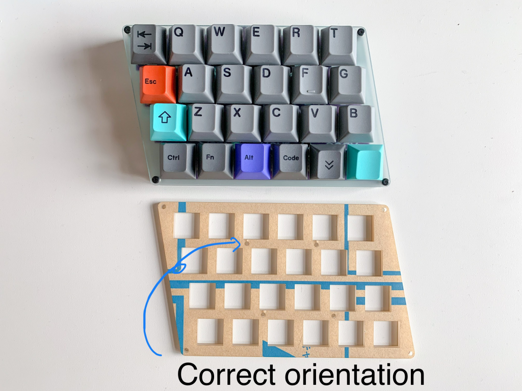
Basic Kit Parts
| Zinc PCB | 2 |
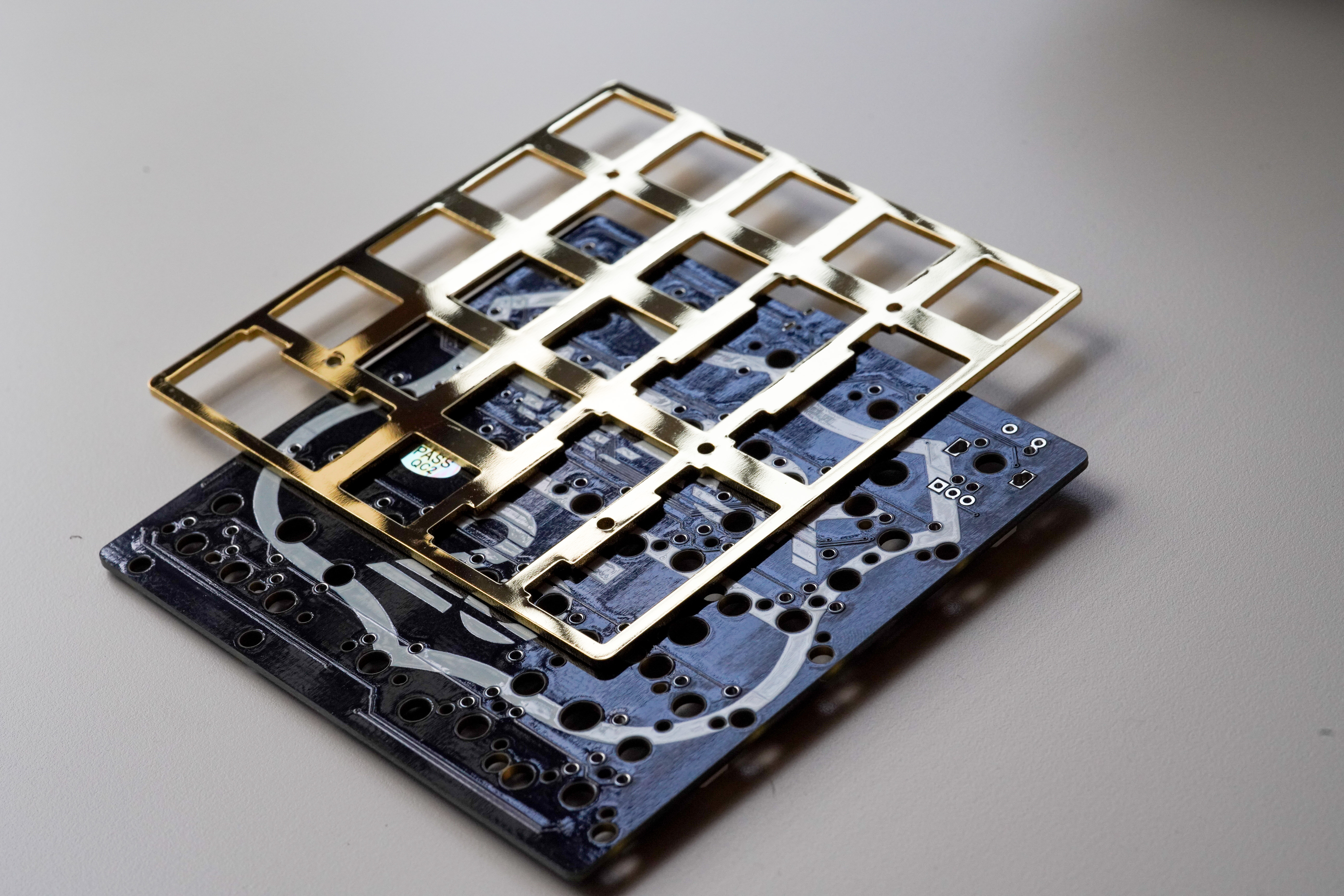
| Acrylic Switch Plate | 2 |
| Acrylic Bottom Plate | 2 |
| Acrylic Large Foot Plate | 2 |
| Acrylic Small Foot Plate | 2 |
| TRRS Jack | 2 |
| Tact Switch | 2 |
| Diode | 48 |
| M2 Screw 5mm (for Switch Plate) | 8 |
| M2 Screw 12mm | 4 |
| M2 Screw 5mm | 20 |
| M2 Screw 8mm | 8 |
| Spacer M2 6mm | 16 |
| Spacer 2mm 3D printed | 8 |
| Cushion Seal (Foot) | 8 |
Also you need:
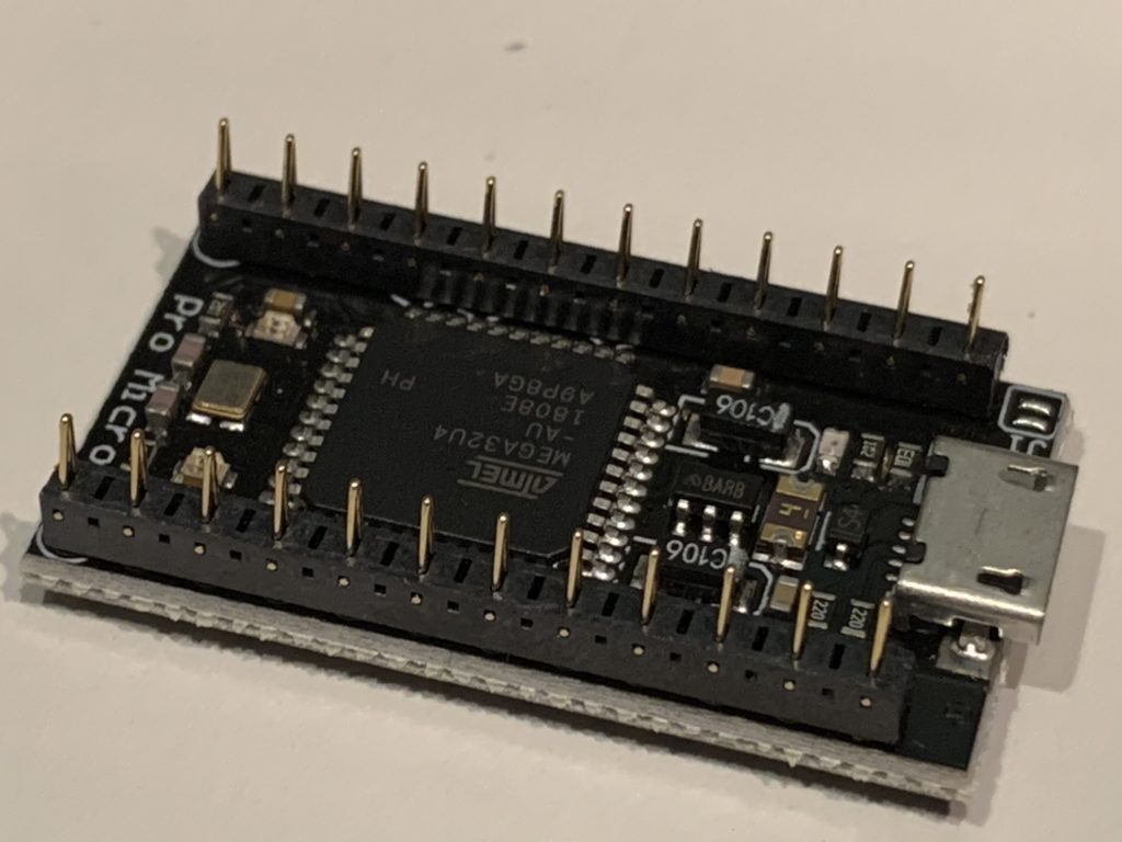
| ProMicro | 2 |
| 12 pin Conthrough detachable Pin header | 4 |
| MX compatible Switch | 48 |
| Keycap | 48 |
| 3.5mm TRS / TRRS cable | 1 |
| USB cable | 1 |
You can solder ProMicro with generic pin header, but I strongly recommend that you install with Conthrough for maintenance work.
Zinc ProMicro Kit includes ProMicro and Conthrough.
Option
| SK6812mini RGB LED | 48 |
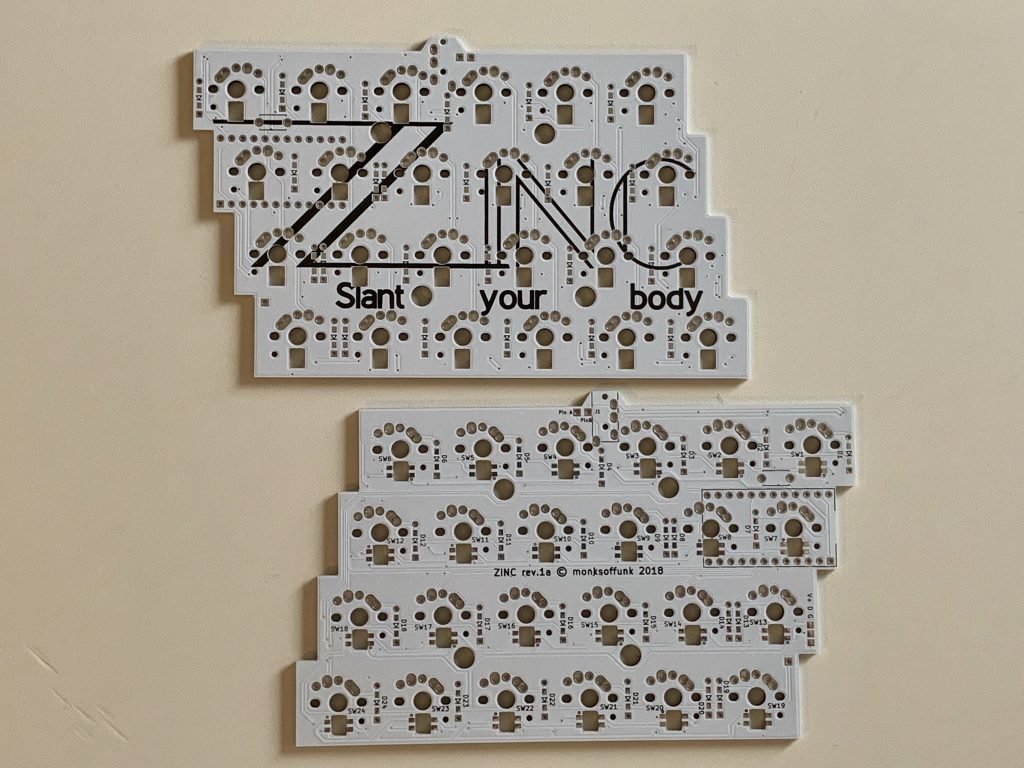
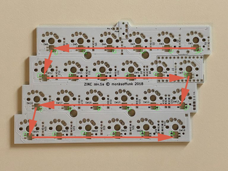
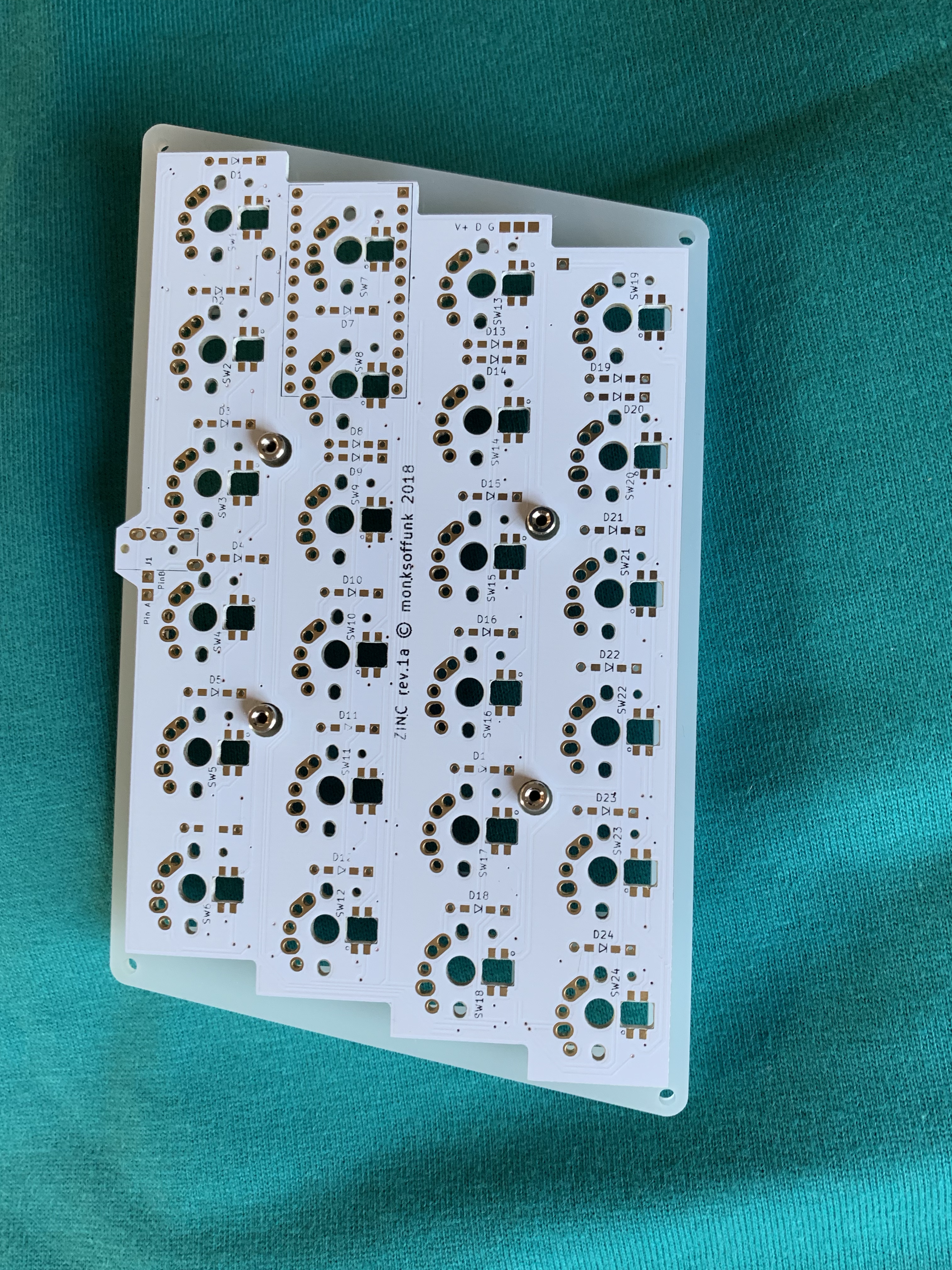
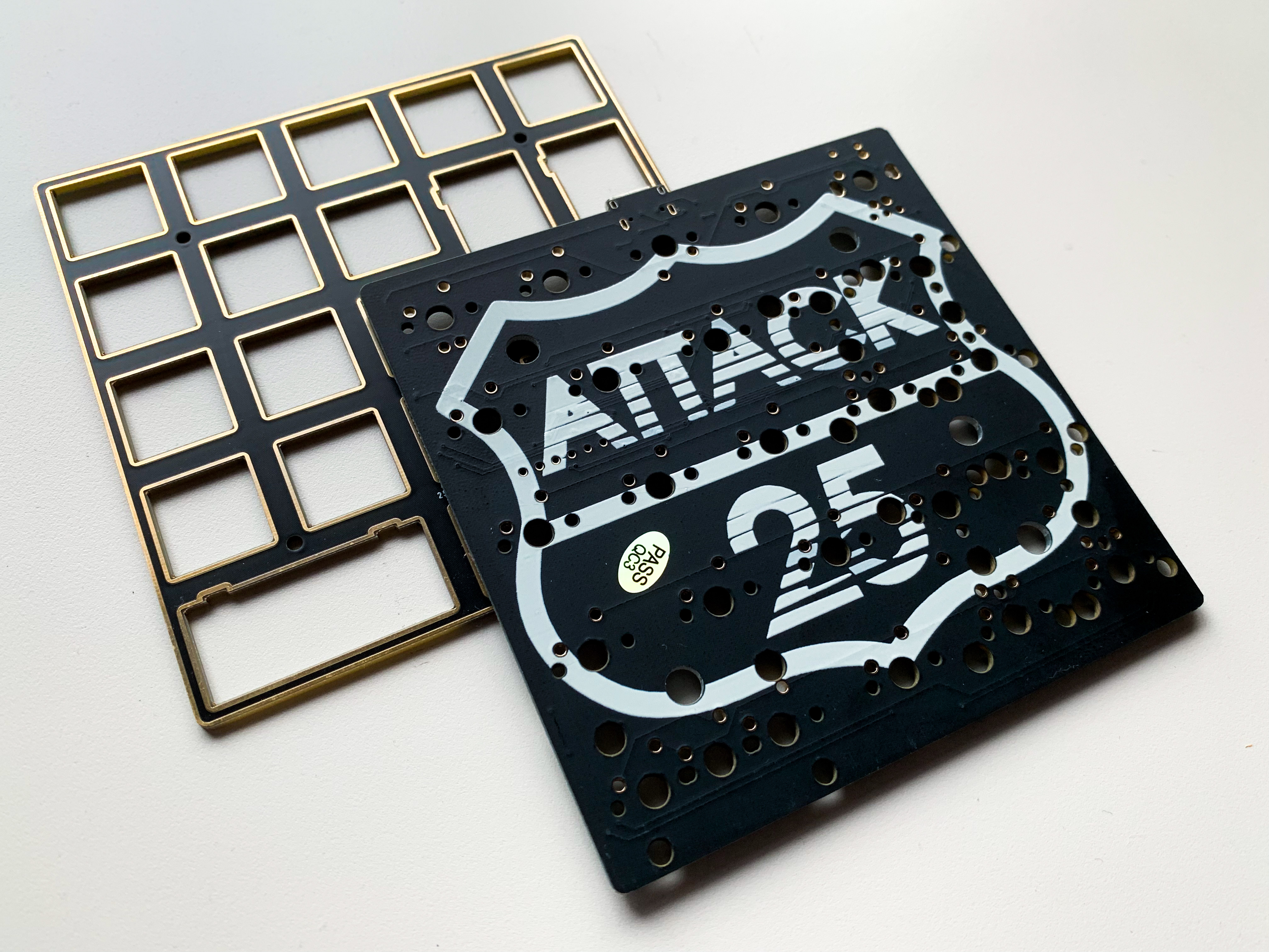
PCB
Circuit Diagram
Build Guide
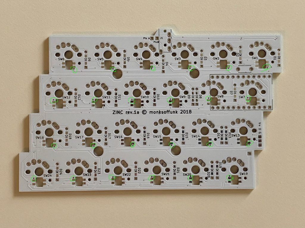
Diodes
Install diodes onto the bottom side of PCB except D7 where ProMicro is located. Install D7 onto the top side (ZINC logo side).
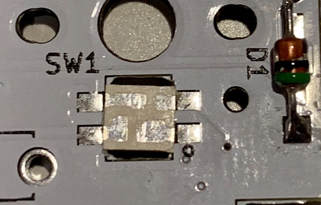
Backlight LED (optional)
[New version] Newer PCB is compatible with SK6812mini-E chip. These chips are easy to hand-solder.
[Old version] Soldering these SK6812mini chps is not easy. Please be careful this step.
- Use soldering iron at low-temperature mode. SK6812mini datasheet says 220 degrees Celcius.
- If more temp, solder them quickly! Or burn out the chips easily.
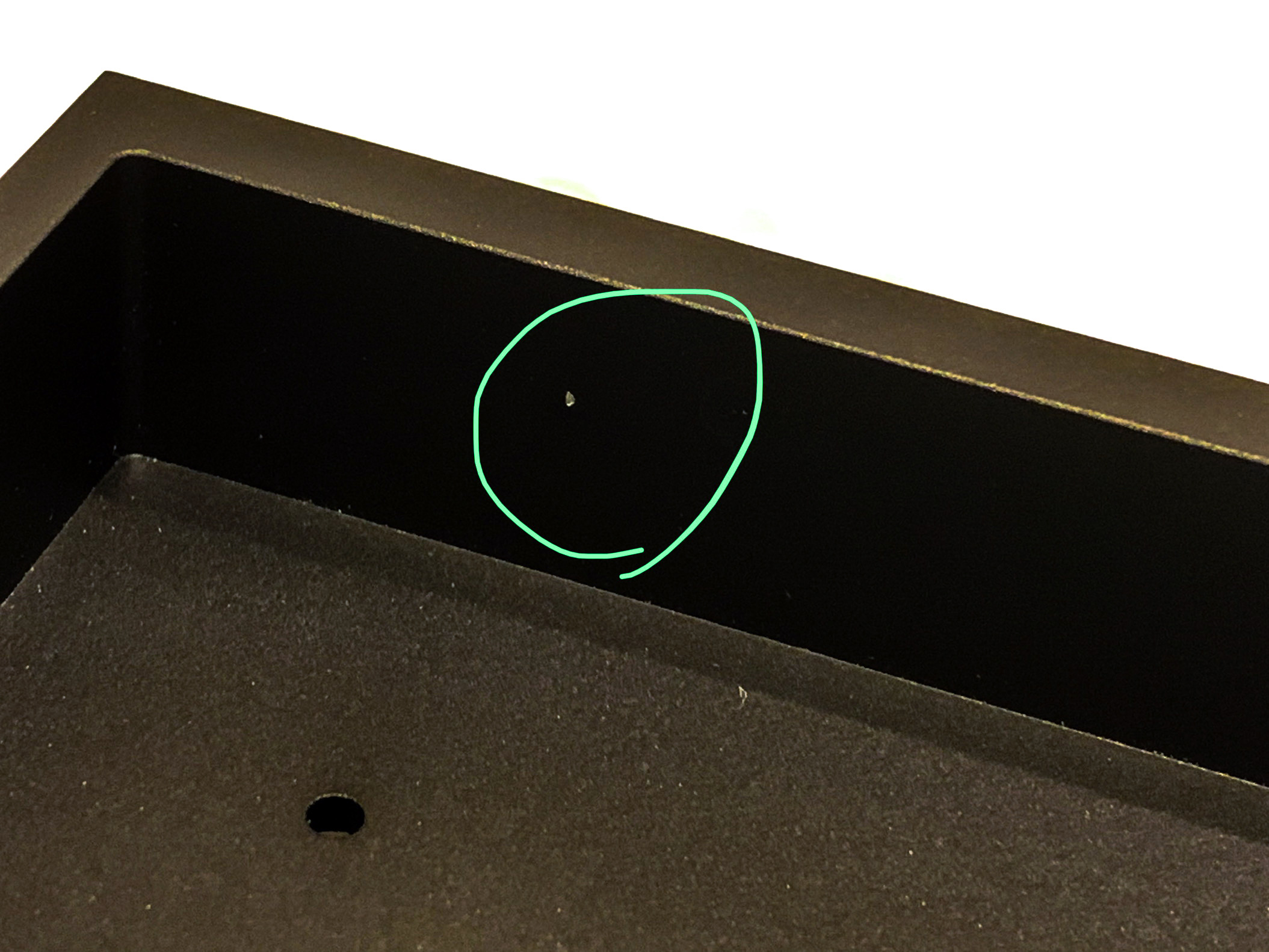
- Verify the orientation. The largest pad of SK6812mini is +5V line. This pad should be the nearest to the circle silk screen on the PCB.
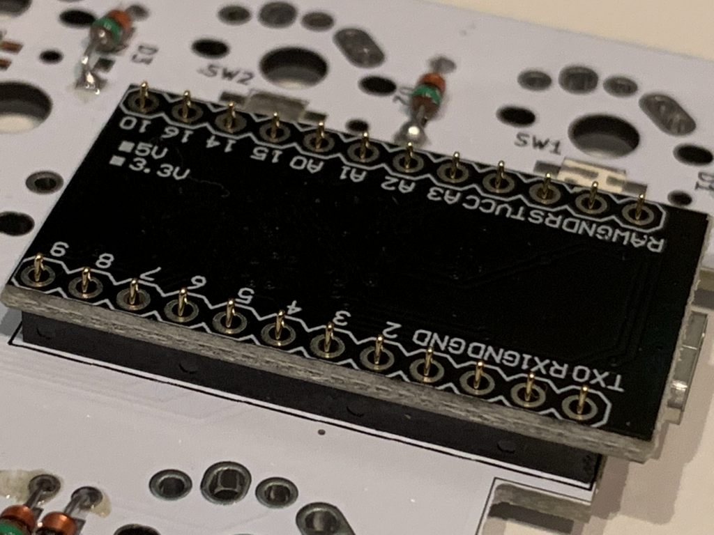
ProMicro
Solder Conthrough spring pin header (that included in Zinc ProMicro Kit) to ProMicro. Conthrough has small windows on one side. Mount both of Conthrough have these small windows facing the same orientation to prevent contact failures.
Don’t solder the Zinc PCB side of Conthrough!!
TRRS Jack and Tact Switch
Install TRRS jack and reset switch onto the bottom side of PCB.
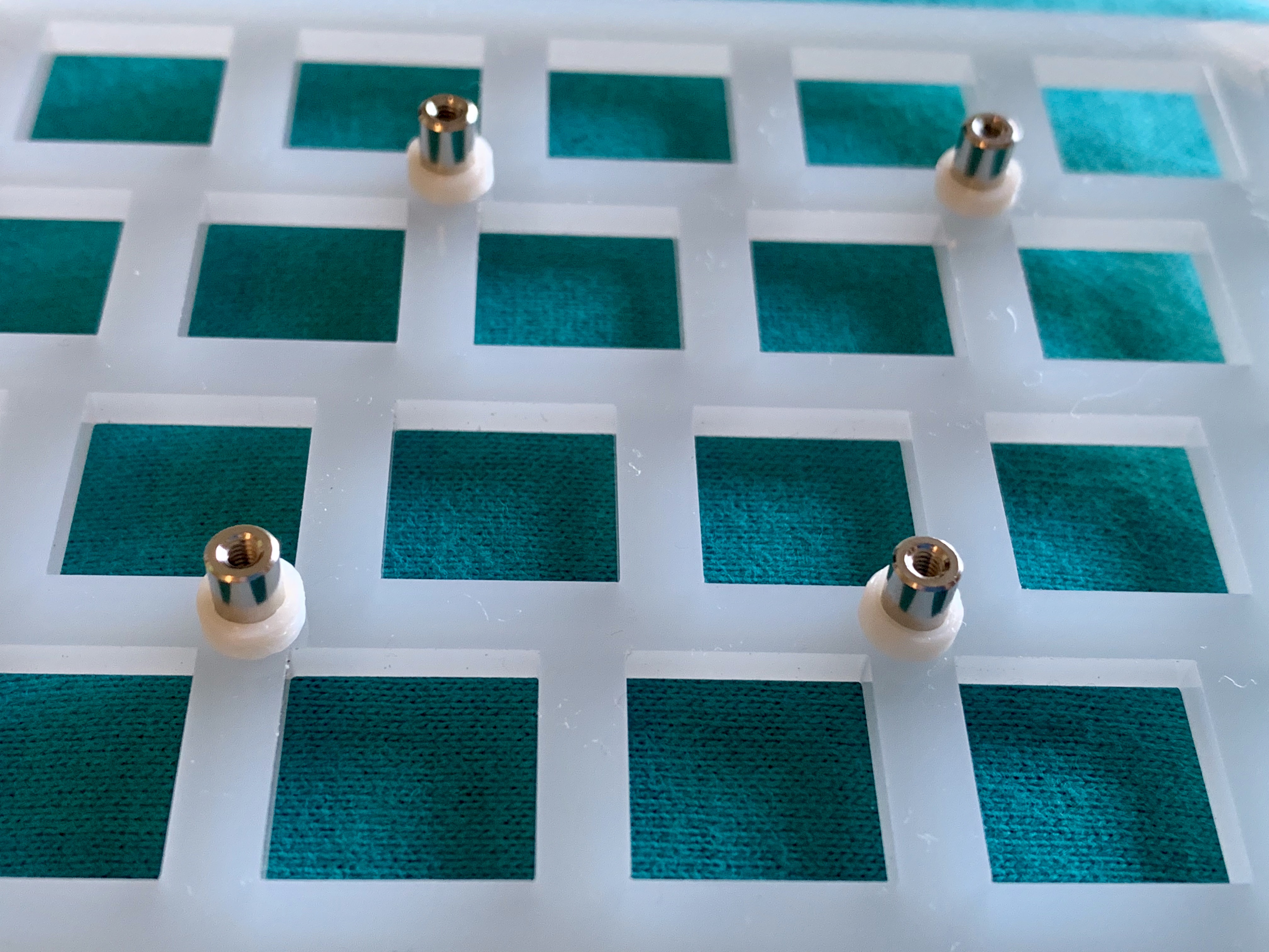
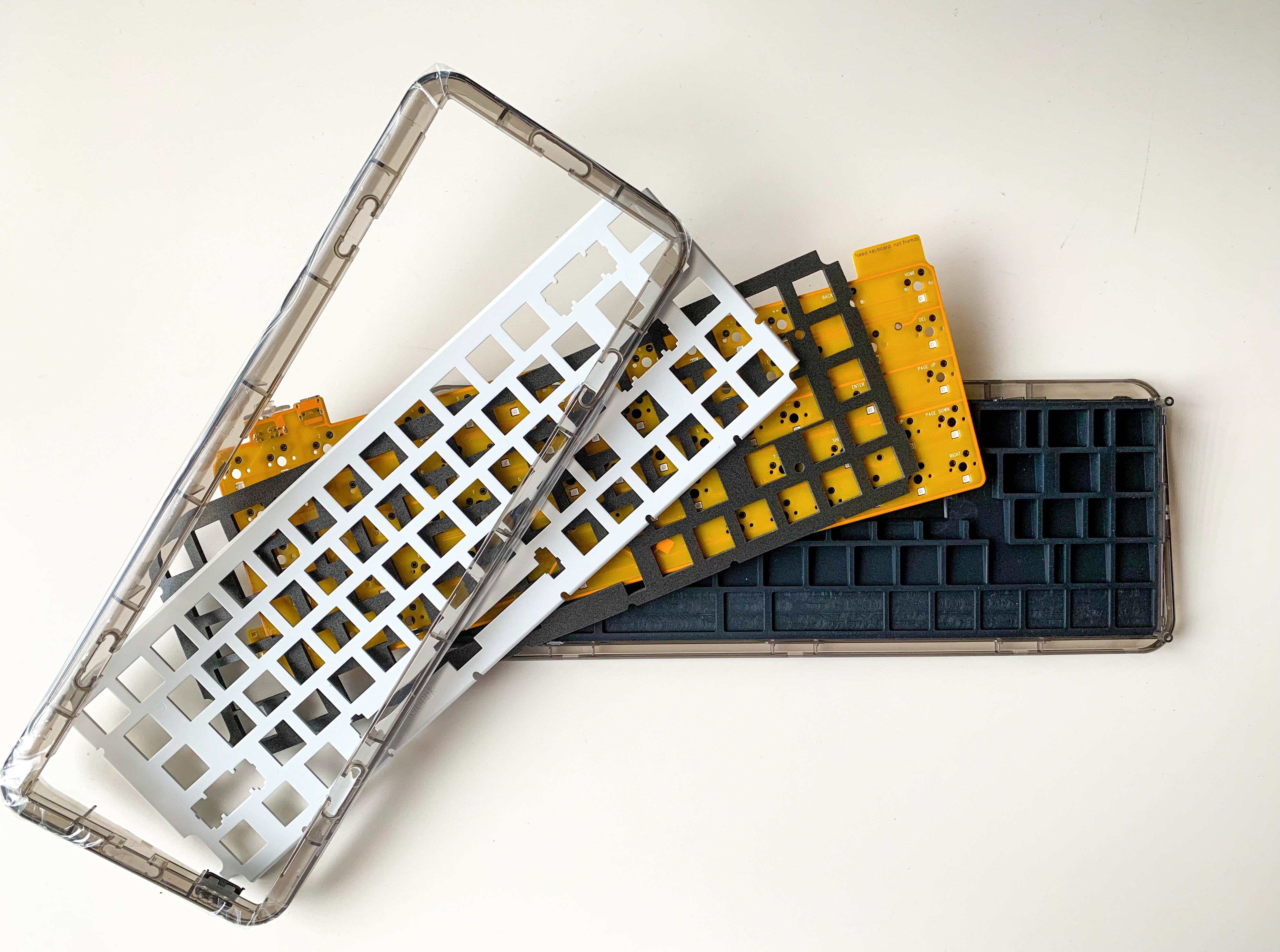
Switch Plate
- Install metal spacers to swtich plate with M2 5mm screws.
- Insert 3D printed pla spacers to 4 metal spacers located the center of the plate.
Key Switch
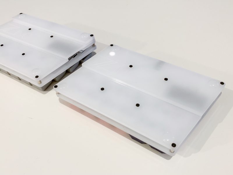
Bottom Plate
Screwd bottom and foot plates.
You may use without small foot plates.
Put cushion seals to the bottom.
Program the fimware
Installing build tools. https://docs.qmk.fm/#/getting_started_build_tools
Build the firmware for zinc
# make zinc:default
# make ZINC=back zinc:default
Finishing touch
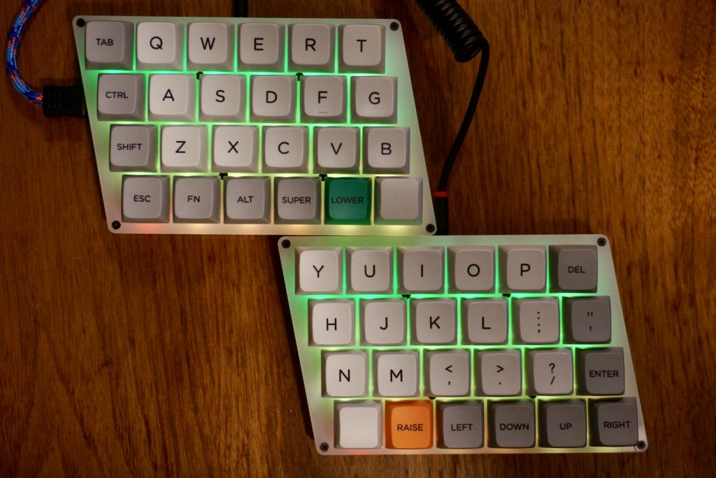
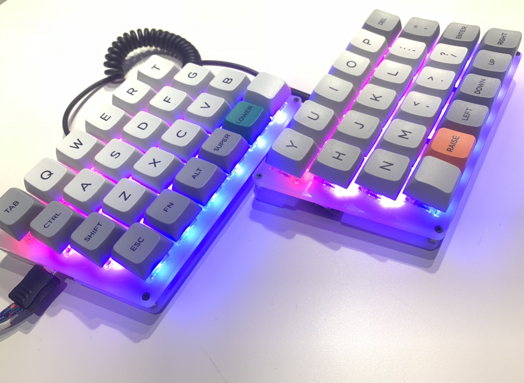
Install your keycaps
Connect the two halves with the TRS or TRRS cable.
Connect a USB cable to left Zinc.
Special thanks to Hasu@TMK, QMK team, Helix keyboard team and foostan who did the first build.
「Zinc Build Guide」に1件のコメントがあります
Zinc buying guide | techsp
(2019-07-16 - 11:16 AM)[…] 13 7月 […]